Tuesday 30 October 2012

Surface Tablet First Impressions

Our office Surface tablet was delivered yesterday and I've the chance to spend a bit of time playing around with it. I thought i'd write a short post about my initial impressions.

I've tried to be as objective as possible. I use Windows as my desktop operating system, however I also own an Ipad and Iphone, both of which I love. This isn't my Surface, it belongs to my employer, so if it sucked, it wouldn't make any difference to me.


The positive.

Build quality is awesome. The surface is a really well made piece of kit.

Touch cover keyboard feels pretty good to type on. With the kickstand out it feels almost like a laptop. Having a track pad is great for doing stuff that requires a higher level of precision.

I've been using Windows 8 on my desktop for the last few months, but it really comes to life on this device. The more I use windows RT on the Surface, the more I prefer it to IOS. Its just a better tablet operating system. Yes there are some flaws. It takes a bit of getting used to the new gestures, but once you do, its amazing.

Multitasking on the surface is amazing. It's liberating to be able to use two apps at the same time with snapped mode. It's easy to keep an eye on twitter while typing up a blog post for example. Switching between apps feels really fluid and natural.

Being able to use Command prompt from the desktop is awesome.

Being able to plug in usb devices is great.

Can add extra storage via the micro sd slot.

The ability to have separate logins for different users of the device is a killer feature. Roaming profile and app data makes for a seamless experience if you use other windows devices.

Much lighter than carrying a laptop around. It feels about the same weight as my Ipad. Maybe just slightly heavier.

This is a device I can actually do some work on without it feeling like a massive chore. I'm writing this post on the surface. I've tried to write blog posts on my Ipad before and it's just a horrible experience.


The negative

Wish the touch cover had a magnetic latch like the ipad

Rotation from landscape to portrait mode feels a little clunky. No transition

Lack of apps at the moment. Its still early days though, hopefully we'll see lots more developers getting on board in the next few months.

Have experienced quite a few crashes in various different apps including the Windows Store. While crashing apps can be blamed on 3rd party developers, there really isn't any excuse for the Windows store crashes I've seen. Sort it out Microsoft!

Windows app store can sometimes be a bit slow.

The mail app is terrible. Again, please sort it out Microsoft.

Having to use IE10 at the moment, although IE10 is actually not so bad. It's still not Chrome. Looking forward to the Chrome metro app.

An out of the box 32gb Surface only has around 17gb disk space free. This is really disappointing. How the hell does Windows RT and Office take up so much space.

The size of the Surface may be off-putting for some people. It's a 10.6 inch tablet. If you primarily use the Ipad in portrait mode, it will definitely feel weird for you. I always use my Ipad in landscape mode so it didn't really bother me.


Overall i'm pretty impressed with the Surface.
It's not perfect but it's definitely got huge potential as a laptop replacement and maybe even an Ipad replacement. Most of the issues I have with it are software based, and can be fixed with updates. It's also important to remember that this is a first generation device. Once there is more app support i'd definitely consider replacing my Ipad with one.

If you want a device purely for content consumption then go buy an Ipad. However if you want a tablet that you can also do some work on then the Surface is a very strong contender.

Sunday 23 September 2012

Real Weather – Digital Sizzle 6 Hackathon Project

Last week i took part in the Digital Sizzle 6 Hackathon, which took place at Mozilla HQ in London.
The event was a 48 hour coffee and beer fuelled event which was organised by the Three Beards.

The brief for the hackathon was relatively simple and open to interpretation. “take publicly accessible data and turn it into something amazing”

The best projects from the hackathon would be displayed at the Whitechapel Gallery in London at an event later in the month.

So on Friday night i headed down to Mozilla HQ along with 3 colleagues from specialmoves. The first night was an opportunity to meet the other developers and creatives at the event and to form a hackathon team ready to start on Saturday. Anyone who had an idea for a project was invited to pitch their idea to the crowd.

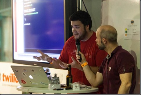
Sid Lawrence talks about twilio

After listening to all the pitches my favourite idea actually came from one of my colleagues Gavin Clark
Basically his idea was to get weather data from a public weather api, and recreate a real live weather experience.

Initially in our beer fuelled state we decided that we wanted to build some sort of booth that we could put the user in, and then shower them with water, and blast them with air etc. A few other people were also interested in Gavin’s idea and we had formed a team of 4 within a relatively short space of time.

Unfortunately our ambitions were possibly a little bit too extreme and somewhat scared the Whitechapel gallery representatives who were present (and also the organisers of the hackathon)

In the end we settled on a slightly more conceptual version of the idea.
The hackathon started on Saturday morning at 9am and teams were allowed until 4pm on Sunday to complete their projects.

We spent the first part of the day planning what we were going to build and then a couple of us headed off to get some materials, while the rest stayed to start writing some code.

Basically our plan was to build an internet connected plug socket that we could switch on and off by making http requests. This would allow us to turn on and off the devices that we were using to simulate the weather. A lamp for the sun, a fan for the wind, a pond pump for rain, and a strobe light for lightning.

I used a .Net gadgeteer mainboard with a relay module and ethernet module to build the plug socket.
Gadgeteer is great for events like this as it is a good platform for rapid prototyping. You can build awesome stuff in a very short space of time, and debugging is really simple with visual studio.

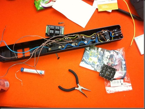
Building an internet connected plug socket

We chose 5 cities from around the world that had fairly interesting weather, and to make things a bit more interesting we allowed users to vote for the city they wanted to see by text message using the awesome Twilio api

Weather data was obtained for the next 10 days using the weather underground api, and the idea was to recreate the next 10 days weather for the winning city over 100 seconds, 10 seconds per day.

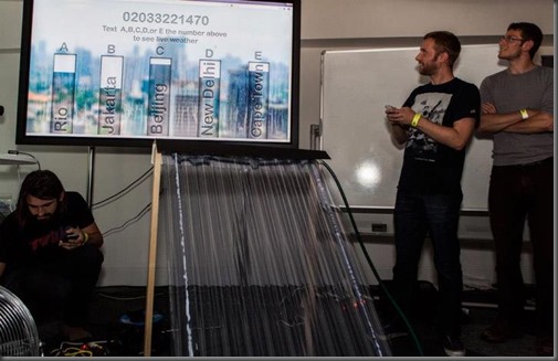
Real Weather in action

We built a node js server side component to handle the twilio stuff and hosted it on a server kindly provided by event sponsors Wirehive.

We also had  videos of the various different weather types and music which was composed by a composer that we met at the event. This was all handled using an Adobe Flash application which coordinated everything and made the required calls to our http enabled plug socket to switch things on and off.

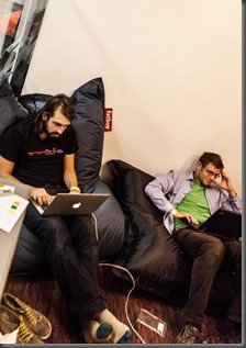
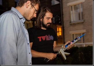
Tom and Gavin write some code  Tom and Gavin with a sealant gun

Digital Sizzle 6 was one of the most amazing events i’ve ever been too. We had lots of fun building Real Weather and met some really cool people along the way. Really can't wait to attend my next hackathon.

Our project and lots of others from Digital Sizzle 6 will be in an exhibition at the Whitechapel Gallery on the 26th September 2012.

Check out a video i made of Real Weather below.

Friday 24 August 2012

Building .Net 4.5 Projects with Jenkins


In my day job for Specialmoves we use Jenkins as our continuous integration server.

Today, after upgrading one of our projects to target .Net 4.5, a colleague of mine was complaining  that the Jenkins build for the project was failing with the following error.

warning MSB3644: The reference assemblies for framework ".NETFramework,Version=v4.5" were not found. To resolve this, install the SDK or Targeting Pack for this framework version or retarget your application to a version of the framework for which you have the SDK or Targeting Pack installed.

He had already tried installing .Net 4.5 on the Jenkins server, which hadn't fixed the problem.


Chuck Norris was not amused....... 


(if you haven't installed the Chuck Norris plugin for Jenkins, i suggest you do so immediately. It wont fix your problem, but it will make you laugh)

The first thing we had to do was to install the Windows SDK for Windows 8 on the Jenkins server. This 
includes the .NET Framework 4.5 SDK


After installing the SDK, we kicked off the build again, only to be greeted with a different error.

error MSB4019:  The imported project "C:\Program Files (x86)\MSBuild\Microsoft\VisualStudio\v11.0\WebApplications\Microsoft.WebApplication.targets" was not found. Confirm that the path in the <Import> declaration is correct, and that the file exists on disk

To fix this error we copied the missing Visual Studio 2012 msbuild folder from a machine that actually had Visual Studio 2012 installed.

So copy C:\Program Files (x86)\MSBuild\Microsoft\VisualStudio\v11.0\ from a machine that has Visual Studio 2012 installed, to the same location on the Jenkins server.

Once you've done this, Jenkins should be able to build the project.

Chuck Norris is happy again.


Tuesday 31 July 2012

Kinect Player Radar Using C# and WPF

In this post i'm going to explain how to make a simple top down player radar for the Kinect using wpf and c#

The radar provides a top down view of user locations relative to the Kinect sensor.


I needed something like this for part of a larger r&d project i'm working on, but wasn't able to find any examples of how to do it. Turns out it's actually pretty simple.

SkeletonStream

The Kinect's SkeletonStream allows us to track the position of a user infront of the Kinect, and also the positions of up to 20 joints on the user's body.

SkeletonStream provides position tracking for up to six users. Full skeletal tracking is only possible for  two users, however for the purposes of this project i only needed the global position of each user.

The Kinect SDK provides a Skeleton Class (Microsoft.Kinect.Skeleton) which is used to contain the data for a tracked user skeleton.

There are three members of the Skeleton Class that we are interested in.

  1. TrackingState : this property tells us the tracking state of the skeleton, either Tracked, PositionOnly, or NotTracked
  2. TrackingId : a unique id for each tracked skeleton
  3. Position : provides the 3d position of a tracked user
Position data is represented by the SkeletonPoint structure which has 3 distance properties, X: which represents the horizontal distance from the sensor, Y: which represents the vertical distance from the sensor, and Z: which represents depth. The values returned are in meters and the Kinect sensor is at position 0,0,0. For this project i was only concerned with the X and Z values as this is a top down view.

For this simple example i'm going to draw a circle on a wcf canvas panel to represent each tracked player. Each player will be represented by a different colored circle.

I'm using a canvas panel with a width of 600px and a height of 1050px
300 pixels on the canvas represents 1 meter in the real world, so the canvas size maps to a 2m x 3.5m area infront of the kinect.
The values i'm using are oriented so that the kinect sensor is effectively at the top center of the canvas

The Code


I'm going to detail some of the code that i used for this project below.
You can find full example code for this article on github

The xaml markup for the radar is very simple. It's pretty much just a canvas panel.

<Window x:Class="KinectPlayerRadar.MainWindow"
        xmlns="http://schemas.microsoft.com/winfx/2006/xaml/presentation"
        xmlns:x="http://schemas.microsoft.com/winfx/2006/xaml"
        Title="KinectPlayerRadar" Width="600" Height="1050" Loaded="WindowLoaded" Closing="WindowClosing">

    <Canvas Width="600" Height="1050" Name="canvas" Background="Gray">
    </Canvas>
</Window>

Jumping straight into the codebehind. First up we define some variables to contain a reference to the Kinect sensor, and a list of the skeleton ids that we are currently tracking.
We then initialize the Kinect sensor, enable the SkeletonStream, and subscribe to the sensor's SkeletonFrameReady event. This event fires when a new skeleton frame for the SkeletonStream is available.

private KinectSensor _sensor;
private List<int> _skeletonTrackingIds;

const int PixelsPerMeter = 300;
const string BaseMarkerName = "player";

private void WindowLoaded(object sender, RoutedEventArgs e)
{
    if (!KinectSensor.KinectSensors.Any())
    {
        throw new ApplicationException("no kinect sensor detected");
    }

    _sensor = KinectSensor.KinectSensors[0];
            
    _skeletonTrackingIds = new List<int>();
            
    _sensor.SkeletonStream.Enable();
    _sensor.SkeletonFrameReady += new EventHandler<SkeletonFrameReadyEventArgs>(sensor_SkeletonFrameReady);            
    _sensor.Start();
}

SkeletonFrameReady event handler

In the event handler we copy the Skeleton Frame data into a new array. The array will always contain 6  Skeletons, even if nothing is being tracked, so we need to loop through each of the Skeletons and check the TrackingState property. If the Skeleton is being tracked we call the SetMarkerPosition method, passing in the Skeleton and its index in the array as parameters.

Once we have processed each skeleton, the RemoveUnusedMarkers method is called to remove any markers for players that are no longer being tracked.


void SkeletonFrameReady(object sender, SkeletonFrameReadyEventArgs e)
{
    Skeleton[] skeletons = new Skeleton[0];

    using (SkeletonFrame skeletonFrame = e.OpenSkeletonFrame())
    {
        if (skeletonFrame != null)
        {
            skeletons = new Skeleton[skeletonFrame.SkeletonArrayLength];
            skeletonFrame.CopySkeletonDataTo(skeletons);
        }
    }

    var index = 0;

    foreach (Skeleton skeleton in skeletons)
    {
        if (skeleton.TrackingState != SkeletonTrackingState.NotTracked)
        {
            SetMarkerPosition(skeleton, index);
        }

        index++;
    }

    RemoveUnusedMarkers(skeletons);
}

SetMarkerPosition 

In this method we get the X and Z positions of the tracked skeleton and calculate the top and left values  for our player marker on the canvas.

The X position is negative if the player is to the right of the sensor, and positive if the user is to the left of the sensor. The Y value will always be positive. So for example an X value of -0.8 and a Y value of 1.5 would mean that the user is 0.8 meters to the left of the sensor, and 1.5 meters back from the sensor.

Given these position values we can easily calculate the position of the marker on the canvas.

Since our sensor is assumed to be at the top center of the canvas, the "top" value for our marker will be skeleton.Position.Z * PixelsPerMeter and the "left" value for our marker will be (canvas.Width / 2) + (skeleton.Position.X * PixelsPerMeter)

If the skeleton is already in our list of tracked skeletons then we simply update the position of the player's marker on the canvas.
If the skeleton is not currently being tracked, we add a new marker to the canvas and then set its position.

private void SetMarkerPosition(Skeleton skeleton, int index)
{         
    System.Windows.Shapes.Ellipse marker;
    var canvasCenter = canvas.Width / 2;
    var top = skeleton.Position.Z * PixelsPerMeter;
    var left = (canvas.Width / 2) + (skeleton.Position.X * PixelsPerMeter);

    if (!_skeletonTrackingIds.Contains(skeleton.TrackingId))
    {
        marker = AddToCanvas(skeleton.TrackingId, index);
        _skeletonTrackingIds.Add(skeleton.TrackingId);
    }
    else
    {
        marker = canvas.FindName(BaseMarkerName + skeleton.TrackingId) as System.Windows.Shapes.Ellipse;
    }

    if (marker != null)
    {
        Canvas.SetTop(marker, (skeleton.Position.Z * PixelsPerMeter));
        Canvas.SetLeft(marker, canvasCenter + (skeleton.Position.X * PixelsPerMeter));
    }
}

AddToCanvas

The AddToCanvas method dynamically adds a new ellipse shape to the canvas to represent our player.

private Ellipse AddToCanvas(int skeletonTrackingId, int skeletonIndex)
{
    var ellipse = new System.Windows.Shapes.Ellipse();
    ellipse.Name = BaseMarkerName + skeletonTrackingId;
    ellipse.Fill = GetMarkerColor(skeletonIndex);
    ellipse.Width = 30;
    ellipse.Height = 30;
            
    canvas.Children.Add(ellipse);
    canvas.RegisterName(ellipse.Name, ellipse);
          
    return ellipse;
}

GetMarkerColor

The GetMarkerColor method returns a different color brush for each possible player index.

private Brush GetMarkerColor(int playerIndex)
{
    if (playerIndex == 1) return Brushes.Blue;
    if (playerIndex == 2) return Brushes.Red;
    if (playerIndex == 3) return Brushes.Green;
    if (playerIndex == 4) return Brushes.Orange;
    if (playerIndex == 5) return Brushes.Purple;

    return Brushes.Turquoise;
}

RemoveUnusedMarkers

The RemoveUnusedMarkers method is called after our player positions have been set in order to remove markers for players that are no longer being tracked.

private void RemoveUnusedMarkers(Skeleton[] skeletons)
{
    _skeletonTrackingIds.ForEach(id =>
        {
            if (!skeletons.Select(s => s.TrackingId).Contains(id))
            {
                var marker = canvas.FindName(BaseMarkerName + id) as Ellipse;
                if (marker != null)
                {
                    canvas.Children.Remove(marker);
                }
            }
        });
}

That's pretty much all there is to it. Obviously this is a very basic example, but hopefully someone else out there might find it useful.

If you liked this article you can also find me on twitter.

Get the code from GitHub

Sunday 15 July 2012

Windows 8 - Cisco VPN Client - Failed to enable virtual adapter

So i installed Windows 8 release preview on my desktop a few days ago and so far i've been quite impressed with it.

One problem that i've come across so far is that after upgrading, Cisco vpn client stopped working with a "Failed to enable Virtual Adapter" error when i tried to connect to any vpn.


This is massively annoying for me as i use Cisco vpn client to connect to the network at work.

Fortunately after some frantic googling i managed to find a workaround.

Fire up the registry editor and navigate to the following path.

HKEY_LOCAL_MACHINE\SYSTEM\CurrentControlSet\Services\CVirtA

Modify the DisplayName key


For 64bit Windows, edit the key so that it reads "Cisco Systems VPN Adapter for 64-bit Windows", or for x86 "Cisco Systems VPN Adapter"


Now open the vpn client and try connecting again. It should work now.

Hopefully this post will save someone else a bit of time.

Thursday 12 July 2012

Unit Testing SignalR Hubs

SignalR is an awesome library for building realtime async applications using .Net. If you've not had a chance to use it yet then you should definately check out this SignalR article from Hanselman and find something to use it in immediately. You're missing out on all the fun!!

So all the cool kids are using SignalR, but I haven't seen many people talking about how to unit test a SignalR hub. In this post i'm going to explain how to set up a testable Hub and then write a sample unit test for it.

I would recommend keeping SignalR Hubs as skinny as possible, and moving as much logic as you can into seperate classes and services. However there will probably be times when you will need to write tests against a hub class, in the same way that we need to write tests against an asp.net mvc Controller.

Lets imagine we have a very simple chat application. In our application, when a message is sent by a client, the message is saved to a data store, and then broadcast to all clients.

This scenario is trivial with SignalR

public class ChatHub : Hub
    {
        private readonly IChatRepository _chatRepository;

        public ChatHub(IChatRepository chatRepository)
        {
            _chatRepository = chatRepository;
        }

        public bool Send(string message)
        {
            _chatRepository.SaveMessage(message, Context.ConnectionId);
            Clients.addMessage(message);
            return true;
        }
    }

In this simple example, i want to test that when a message is sent, the SaveMessage method is invoked on _chatRepository with the correct parameters and that the Send method returns true.

In order to test this we need to create a testable instance of ChatHub.

If we try to new up a ChatHub instance in a unit test, we'll get null reference exceptions from both Context.ConnectionId, and Clients.addMessage when Send is called.

We need to wire up the Context and Clients properties of the Hub.
It will also be useful to wire up the Caller property as this will likely be used at some point.

I'm using Moq in this example to mock the various different objects required to create a testable hub.

 public class TestableChatHub : ChatHub  
   {  
     public Mock<IChatRepository> MockChatRepository { get; private set; }
  
     public TestableChatHub(Mock<IChatRepository> mockChatRepository)  
       : base(mockChatRepository.Object)  
     {
       const string connectionId = "1234";  
       const string hubName = "Chat";  
       var mockConnection = new Mock<IConnection>();  
       var mockUser = new Mock<IPrincipal>();  
       var mockCookies = new Mock<IRequestCookieCollection>();
  
       var mockRequest = new Mock<IRequest>();  
       mockRequest.Setup(r => r.User).Returns(mockUser.Object);  
       mockRequest.Setup(r => r.Cookies).Returns(mockCookies.Object);
         
       Clients = new ClientAgent(mockConnection.Object, hubName);  
       Context = new HubCallerContext(mockRequest.Object, connectionId);
  
       var trackingDictionary = new TrackingDictionary();  
       Caller = new StatefulSignalAgent(mockConnection.Object, connectionId, hubName, trackingDictionary);  
     }  
   } 

Once the Context, Clients and Caller properties have been set on the Hub, writing tests against it is simple.

 using Moq;  
 using NUnit.Framework;  
 using SignalRTestableHubExample.Models;
  
 namespace SignalRTestableHubExample.Tests  
 {   
   [TestFixture]  
   public class ChatHubTests  
   {  
     private TestableChatHub _hub;
  
     [SetUp]  
     public void SetUpTests()  
     {  
       _hub = GetTestableChatHub();  
     }
  
     [Test]  
     public void ExampleTest()  
     {  
       const string message = "test";  
       const string connectionId = "1234";
  
       var result = _hub.Send(message);
  
       _hub.MockChatRepository.Verify(r => r.SaveMessage(message, connectionId));
       Assert.IsTrue(result);  
     }
  
     private TestableChatHub GetTestableChatHub()  
     {  
       var mockRepository = new Mock<IChatRepository>();  
       mockRepository.Setup(m => m.SaveMessage(It.IsAny<string>(), It.IsAny<string>())).Returns(true);  
       return new TestableChatHub(mockRepository);  
     }  
   }  
 }

Friday 6 July 2012

.Net Gadgeteer Robot with PS Vita as controller

This post is about a modification of my .Net Gadgeteer object tracking robot.

The aim of the project was to add a robotic arm to the robot and allow control over wifi using my Playstation Vita.

I had picked up a Playstation Vita a few months back and was really excited when i heard about the Playstation Mobile Developer Program because it would allow me to write code for the vita in c#

After building my object tracking robot, i thought it would be an interesting challenge to try and control it using the vita.

The robot uses the same Rover 5 chassis and explorer pcb motor controller as the original robot.


Here's a couple of videos of him in action.


The parts i used to build this robot were as follows.
  • Fez Spider Mainboard
  • 2 Gadgeteer Extender Modules
  • Gadgeteer Ethernet Module
  • Gadgeteer Client DP Module
  • Dagu 2dof Robotic Arm
  • Dagu Rover 5 Chassis
  • Dagu Explorer PCB
  • Edimax Portable Router
I'm using a Playstation Vita as the controller for this robot, however you could really use any wifi capable device that you can write a socket client for.


I was planning on picking up a Gadgeteer wifi module for this project, however instead i decided to use this portable router that i had lying around.

The gadgeteer ethernet module connects directly into the portable router while the vita connects to the the router over wifi.
Its kinda cool because the robot has its own self contained network and i dont need to rely on having an external router present in order to use it.


The battery lasts for about 4 hours and i think you can pick these up pretty cheap now.


My rough plan was to run a socket server on the robot which would listen for commands from a socket client running on the ps vita and to use a couple of existing libraries i have made for controlling the motors and robotic arm.

I've explained in previous posts about the chassis and motor controller that i'm using, so i wont go into any more detail about that here.

Breadboard Diagram.

This is how i have wired everything up on a breadboard using the 2 extender modules.
I have soldered headers onto both extender modules to make it easy for me to plug them into a breadboard.

Both extender modules need to be connected to pwm capable sockets on the gadgeteer mainboard. I'm using sockets 8 and 11 on the Spider.


Code

In order to keep things tidy i created a few seperate class librarys for things that i can reuse in other gadgeteer projects.

I'm using the RoboticArmController class, that i detailed in a previous blog post, to control the robotic arm.

I also have a MotorController class which i will detail below. This class is used to drive the motors of the robot. 

I pass in a reference to an extender module in the constructor and set up the pwm and digital outputs that i will need to control the motors. The extender module used to drive the motors will need to be connected to a pwm capable socket on the gadgeteer mainboard.

The MotorController class has a single public method: DriveMotor(int speed, Motor motor) which is used to drive either the left or right motor. The speed ranges from -100 which is reverse, to 100 which is full speed forwards, with 0 being stop.

using System;
using GT = Gadgeteer;
using Gadgeteer.Modules.GHIElectronics;

namespace GadgeteerPwmMotorController
{
    public class MotorController
    {
        public enum Motor
        {
            left, right
        }

        public const int MotorMaxSpeed = 100;
        public const int MotorMinSpeed = -100;
        private uint _pwmPulsePeriod;

        public GT.Interfaces.PWMOutput LeftMotorPwm { get; set; }

        public GT.Interfaces.PWMOutput RightMotorPwm { get; set; }

        public GT.Interfaces.DigitalOutput LeftMotorDirection { get; set; }

        public GT.Interfaces.DigitalOutput RightMotorDirection { get; set; }

        public MotorController(Extender extender, uint pwmPulsePeriod)
        {
            if (extender == null)
            {
                throw new ApplicationException("motor controller pwm extender module not set up correctly");
            }

            LeftMotorPwm = extender.SetupPWMOutput(GT.Socket.Pin.Eight);
            RightMotorPwm = extender.SetupPWMOutput(GT.Socket.Pin.Seven);
            LeftMotorDirection = extender.SetupDigitalOutput(GT.Socket.Pin.Six, true);
            RightMotorDirection = extender.SetupDigitalOutput(GT.Socket.Pin.Five, true);

            _pwmPulsePeriod = pwmPulsePeriod;
        }

        public void DriveMotor(int speed, Motor motor)
        {
            // speed range is from -100 to 100
            // -100 is full speed reverse, 0 is stop, 100 is full speed forwards

            bool forward = true;

            speed = speed > MotorMaxSpeed ? MotorMaxSpeed : speed;

            speed = speed < MotorMinSpeed ? MotorMinSpeed : speed;

            if (System.Math.Abs(speed) < 7) speed = 0; 

            if (speed < 0)
            {
                forward = false;
            }

            if (motor == Motor.left)
            {
                LeftMotorDirection.Write(forward);
                SetPwmPulse(LeftMotorPwm, speed);
            }
            else
            {
                RightMotorDirection.Write(forward);
                SetPwmPulse(RightMotorPwm, speed);
            }
        }

        private void SetPwmPulse(GT.Interfaces.PWMOutput pwm, int speed)
        {
            var pulseHighTime = System.Math.Abs(speed) * (_pwmPulsePeriod / 100);
            pwm.SetPulse(_pwmPulsePeriod, (uint)pulseHighTime);
        }
    }
}

UdpSocketServer Class

I figured it would be better to use Udp for communication between the robot and the vita.
I wasn't too bothered about losing the occasional packet and i wanted it to be as fast as possible so that control of the robot would feel responsive.

I created a UdpSocketServer class which manages the task of listening for Udp data on a specified port.

It is a very simple class that listens for a socket connection on the specified port in a seperate thread so not to block the rest of the program. When data is recieved an event is raised.

 using System;  
 using System.Net;  
 using System.Net.Sockets;  
 using System.Threading;  
 using Microsoft.SPOT;  
 namespace SocketServer  
 {  
   public class UdpSocketServer  
   {  
     private Thread _listeningThread;  
     private int _port;  
     public delegate void DataReceivedEventHander(object sender, byte[] data);  
     public event DataReceivedEventHander DataReceived;  
     public UdpSocketServer(int port)  
     {  
       _port = port;  
     }  
     public void StartListening()  
     {  
       _listeningThread = new Thread(new ThreadStart(Listen));  
       _listeningThread.Start();  
     }  
     public void StopListening()  
     {  
       if (_listeningThread != null)  
       {  
         _listeningThread.Abort();  
       }  
     }  
     private void Listen()  
     {  
       using (var socket = new Socket(AddressFamily.InterNetwork, SocketType.Dgram, ProtocolType.Udp))  
       {  
         EndPoint ipEndPoint = new IPEndPoint(IPAddress.Any, _port);  
         socket.Bind(ipEndPoint);  
         while (true)  
         {  
           if (socket.Poll(-1, SelectMode.SelectRead))  
           {  
             byte[] data = new byte[socket.Available];  
             int i = socket.ReceiveFrom(data, ref ipEndPoint);  
             if (data.Length > 0)  
             {  
               DataReceived(this, data);  
             }  
           }  
         }  
       }  
     }  
   }  
 }  

Putting it all together

With these utility classes in place, the rest of the code is relatively straight forward.

I set up a new Gadgeteer project in visual studio and added the 2 extender modules and Ethernet module using the visual designer.

Added a class to contain the control data received from the vita

 public class ControlData  
   {  
     public int LeftMotor { get; set; }  
     public int RightMotor { get; set; }  
     public bool CloseClaw { get; set; }  
     public bool OpenClaw { get; set; }  
     public bool ArmUp { get; set; }  
     public bool ArmDown { get; set; }  
   }  

Created a  VitaControlListener class to manage dealing with the socket server and reading the data received from the vita.

On the vita i'm using the left analog stick to control the left motor, and the right analog stick to control the right motor. The d-pad up and down buttons are used to move the robotic arm up and down, the left shoulder button opens the claw, and the right should button closes it.

The joystick and button values are read on the vita and sent to the socket server on the robot as a byte array. The VitaControlListener class subscribes to the DataReceived event of the socket server, extracts the control values from the byte array, and puts them into a ControlData object for us to work with. 


 using System;  
 using System.Net;  
 using System.Net.Sockets;  
 using System.Threading;  
 using Microsoft.SPOT;  
 using SocketServer;  
 namespace VitaControlledRobot  
 {  
   class VitaControlListener  
   {  
     private UdpSocketServer _socketServer;  
     public delegate void ControlDataReceivedEventHander(object sender, ControlData data);  
     public event ControlDataReceivedEventHander ControlDataReceived;  
     public VitaControlListener()  
     {  
       _socketServer = new UdpSocketServer(11000);  
       _socketServer.DataReceived += new UdpSocketServer.DataReceivedEventHander(_socketServer_DataReceived);  
     }  
     void _socketServer_DataReceived(object sender, byte[] data)  
     {  
       ReadControlData(data);  
     }  
     public void Start()  
     {  
       _socketServer.StartListening();  
     }  
     public void Stop()  
     {  
       _socketServer.StopListening();  
     }  
     private void ReadControlData(byte[]data)  
     {  
       float left;  
       float right;  
       GHIElectronics.NETMF.System.Util.ExtractValueFromArray(out left, data, 0);  
       GHIElectronics.NETMF.System.Util.ExtractValueFromArray(out right, data, 4);  
       ControlDataReceived(this, new ControlData  
       {  
         LeftMotor = GetSpeedFromJoystickValue(left),  
         RightMotor = GetSpeedFromJoystickValue(right),  
         OpenClaw = data[9] > 0,  
         CloseClaw = data[10] > 0,  
         ArmUp = data[11] > 0,  
         ArmDown = data[12] > 0  
       });  
     }  
     private int GetSpeedFromJoystickValue(float joystickValue)  
     {  
       var speed = (int)(joystickValue * -100);  
       return System.Math.Abs(speed) < 7 ? 0 : speed;  
     }  
   }  
 }  

And finally in Program.cs.

Basically all we are doing in here is listening for events from a VitaControlListener instance and using the RoboticArmController and MotorController classes to control the robotic arm and the movement of the robot depending on what control data was received.

I've given the robot a static ip address and hardcoded the networking details for testing purposes.


 using System;  
 using System.Threading;  
 using Microsoft.SPOT;  
 using Gadgeteer.Networking;  
 using GT = Gadgeteer;  
 using GTM = Gadgeteer.Modules;  
 using GadgeteerPwmMotorController;  
 using GadgeteerRoboticArm;  
 namespace VitaControlledRobot  
 {  
   public partial class Program  
   {      
     private const string IpAddress = "192.168.2.150";  
     private const string SubnetMask = "255.255.255.0";  
     private const string DefaultGateway = "192.168.2.1";  
     private const uint PwmPulsePeriod = 20000000;  
     private const int ClawPositionStep = 25;  
     private const int ArmPositionStep = 10;
  
     private MotorController _motorController;  
     private RoboticArmController _roboticArmController;  
     private VitaControlListener _vitaListener;
  
     void ProgramStarted()  
     {  
       Debug.Print("Program Started");  
       Setup();  
     }
  
     private void Setup()  
     {  
       ethernet.UseStaticIP(IpAddress, SubnetMask, DefaultGateway);  
       ethernet.NetworkUp += new GTM.Module.NetworkModule.NetworkEventHandler(ethernet_NetworkUp);  
       ethernet.NetworkDown += new GTM.Module.NetworkModule.NetworkEventHandler(ethernet_NetworkDown);  
     }
  
     void ethernet_NetworkDown(GTM.Module.NetworkModule sender, GTM.Module.NetworkModule.NetworkState state)  
     {  
       _vitaListener.Stop();  
     }
  
     void ethernet_NetworkUp(GTM.Module.NetworkModule sender, GTM.Module.NetworkModule.NetworkState state)  
     {  
       Debug.Print("network up");  
       Debug.Print(ethernet.NetworkSettings.IPAddress);
  
       _motorController = new MotorController(PwmExtender2, PwmPulsePeriod);  
       _roboticArmController = new RoboticArmController(PwmExtender, GT.Socket.Pin.Seven, GT.Socket.Pin.Eight, PwmPulsePeriod);  
       _vitaListener = new VitaControlListener();
  
       _vitaListener.ControlDataReceived += new VitaControlListener.ControlDataReceivedEventHander(vitaListener_ControlDataReceived);  
       _vitaListener.Start();
  
       Debug.Print("server started");  
     }
  
     void vitaListener_ControlDataReceived(object sender, ControlData data)  
     {  
       _motorController.DriveMotor(data.LeftMotor, MotorController.Motor.left);  
       _motorController.DriveMotor(data.RightMotor, MotorController.Motor.right);  
       if (data.CloseClaw)  
       {  
         _roboticArmController.MoveClaw(_roboticArmController.ClawCurrentPosition + ClawPositionStep);  
       }  
       else if(data.OpenClaw)  
       {  
         _roboticArmController.MoveClaw(_roboticArmController.ClawCurrentPosition - ClawPositionStep);  
       }  
       if (data.ArmUp)  
       {  
         _roboticArmController.MoveArm(_roboticArmController.ArmCurrentPosition + ArmPositionStep);  
       }  
       else if (data.ArmDown)  
       {  
         _roboticArmController.MoveArm(_roboticArmController.ArmCurrentPosition - ArmPositionStep);  
       }  
     }  
   }  
 }  

Thats mostly it on the gadgeteer side.

Obviously this is a work in progress and there are lots of other things that i want to add to it, but i'm quite happy with how it's worked out so far.

I love how easy it is to do stuff like this with Gadgeteer.

In my next post i'll be showing what the ps vita side looks like.

If you liked this post you can also find me on twitter @RikTheManc

Gadgeteer Robotic Arm Controller

In this post i'm going to explain how to control a small 2dof robotic arm using .Net Gadgeteer.


The parts i am using for this project are
  • Fez Spider Mainboard
  • Dagu 2dof Robotic Arm
  • Gadgeteer Extender Module
  • Gadgeteer Button Module to control the gripper
  • Gadgeteer Potentiometer Module to control the arm.
The robotic arm consists of a gripper and two servos, the first servo controls the movement of the gripper, and the other moves the arm up or down (or left/right depending on how you mount it)

You could very easily adapt the code in this post to deal with a larger robotic arm with more servos.

Here is a quick video of the robotic arm in action. It's currently attached to the front of my gadgeteer robot.

Setting up the robotic arm


In order to wire up the Robotic arm i'm using an extender module with a header soldered onto it so that i can plug it into a breadboard easily.


First up the extender module needs to be connected to a pwm capable socket on the mainboard.
I used socket 8 on the Spider. Pins 7 and 8 on the extender module will be connected to the pwm connectors on the servos. The pwm connectors are orange. Positive is red and Ground is the brown connector.

We need to use a separate power source for the servos. Don't try and power them from the extender module. A battery pack of 4AA batteries or similar will work fine.

Our breadboard should be wired up as shown to the left.


Once everything is connected it's pretty simple to write some code to move the servos.

The only tricky part was figuring out the correct pwm values to send to the gripper servo in order to fully open and close it. This just required a bit of trial and error. The gripper servo can only move around 60 degrees because it is constrained by the gripper mechanism. If you try to move it too far beyond its limits, the servo will heat up extremely fast. The arm servo can move through 180 degrees.

I made a small class which simplifies use of the arm with gadgeteer, and can be re-used in other projects.

In the constructor of the RoboticArmController class we pass in a reference to the extender module, and specify which pins will be used for the gripper and the arm.

There are public methods which can be used to move the position of the gripper and arm. The position value passed to these methods should be in the range of 0 - 100. At position 0 the gripper is fully open, and at 100 it is fully closed.

 using System;  
 using Microsoft.SPOT;  
 using Gadgeteer.Modules.GHIElectronics;  
 using GT = Gadgeteer;  
 namespace GadgeteerRoboticArm  
 {  
   public class RoboticArmController  
   {  
     private const int ClawPwmMin = 1500;  
     private const int ClawPwmMax = 2200;  
     private const int ArmPwmMin = 600;  
     private const int ArmPwmMax = 2400;
  
     private const int ClawPositionMax = 100;  
     private const int ClawPositionMin = 0;  
     private const int ArmPositionMax = 100;  
     private const int ArmPositionMin = 40; 
 
     private uint _pwmPulsePeriod;  
     private GT.Interfaces.PWMOutput _clawPwm;  
     private GT.Interfaces.PWMOutput _armPwm; 
 
     public int ClawCurrentPosition { get; private set; }  
     public int ArmCurrentPosition { get; private set; } 
 
     public RoboticArmController(Extender extender, GT.Socket.Pin clawPin, GT.Socket.Pin armPin, uint pwmPulsePeriod)  
     {  
       if (extender == null)  
       {  
         throw new ApplicationException("robotic arm pwm extender not set up correctly");  
       }  
       _pwmPulsePeriod = pwmPulsePeriod;  
       _clawPwm = extender.SetupPWMOutput(clawPin);  
       _armPwm = extender.SetupPWMOutput(armPin);  
       Reset();  
     }
  
     public void Reset()  
     {  
       MoveClaw(ClawPositionMin);  
       MoveArm(ArmPositionMin);  
     } 
 
     public void MoveClaw(int position)  
     {  
       ClawCurrentPosition = Move(_clawPwm, position, ClawPositionMin, ClawPositionMax, ClawPwmMin, ClawPwmMax);  
     }
  
     public void MoveArm(int position)  
     {  
       ArmCurrentPosition = Move(_armPwm, position, ArmPositionMin, ArmPositionMax, ArmPwmMin, ArmPwmMax);  
     } 
 
     private int Move(GT.Interfaces.PWMOutput pwm, int position, int minPosition, int maxPosition, int pwmMin, int pwmMax)  
     {  
       position = position > maxPosition ? maxPosition : position;  
       position = position < minPosition ? minPosition : position;
  
       Servo(pwm, GetPwmPulseValue(pwmMax, pwmMin, position));
  
       return position;  
     } 
 
     private int GetPwmPulseValue(int max, int min, int position)  
     {  
       return (min + (((max - min) / 100) * position)) * 1000;  
     }
  
     private void Servo(GT.Interfaces.PWMOutput pwm, int pwmPulseHighTime)  
     {  
       pwm.SetPulse(_pwmPulsePeriod, (uint)pwmPulseHighTime);  
     }  
   }  
 }  

Using this class it is then easy to set up a demo application that closes and opens the gripper as a button is pressed and released, and moves the arm position dependant on the position of a potentiometer module.

Create a new Gadgeteer project in visual studio, add the the button, potentiometer and extender modules using the visual designer and then add the following code to Program.cs

 using System;  
 using System.Threading;  
 using Microsoft.SPOT;  
 using GT = Gadgeteer;  
 using Gadgeteer.Modules.GHIElectronics;  
 using GadgeteerRoboticArm;  
 namespace RoboticArmDemo  
 {  
   public partial class Program  
   {  
     private RoboticArmController _roboticArmController;  
     private GT.Timer _timer; 
 
     void ProgramStarted()  
     {  
       Debug.Print("Program Started");  
       _roboticArmController = new RoboticArmController(extender, GT.Socket.Pin.Seven, GT.Socket.Pin.Eight, 20000000);
  
       button.ButtonPressed += new Button.ButtonEventHandler(button_ButtonPressed);  
       button.ButtonReleased +=new Button.ButtonEventHandler(button_ButtonReleased);
  
       _timer = new GT.Timer(500);  
       _timer.Tick += new GT.Timer.TickEventHandler(_timer_Tick);      
     }
  
     void _timer_Tick(GT.Timer timer)  
     {  
       _roboticArmController.MoveArm((int)potentiometer.ReadPotentiometerPercentage());  
     }
  
     void button_ButtonPressed(Button sender, Button.ButtonState state)  
     {  
       _roboticArmController.MoveClaw(100);  
     }
  
     void button_ButtonReleased(Button sender, Button.ButtonState state)  
     {  
       _roboticArmController.MoveClaw(0);  
     }  
   }  
 }  

And thats pretty much all there is to it.

When the program is started, pressing and holding the button will close the gripper. Releasing the button will open the gripper again.


The position of the arm can be set using the potentiometer.


You can grab sample code to accompany this post from github

Wednesday 20 June 2012

DIY City - Interactive html5 projection

Just got back from a demo of an r&d project i've been working on for the past couple of weeks in collaboration with Usman Haque and Specialmoves

The project was an interactive projection that allowed users to interact with a projection of 8 bit sprites onto the walls of our office building, using their mobile devices.

We built a mobile web application  using jquery mobile, .net mvc and signalr

The actual projection was all done using html5 canvas and node js

Tonight was a very early alpha demo of the work we've done so far.

Watching around 50 people all interacting with the projection in realtime using their smartphones was amazing.

Can't wait to try doing this on a larger scale. Can imagine it would be amazing doing it at something like a music festival.

We came up against lots of interesting technical challenges while doing this project.

I'll do a follow up post with some more technical information soon. In the meantime you can check out some photos taken during the demo.


Tuesday 29 May 2012

Vita controlled Gadgeteer robotic arm

This is just a very quick post with a video of another robot project i'm working on.

This one is a PS Vita controlled robot.

The vita code is in c# using the awesome PS Suite SDK and basically just sends commands to the robot using udp sockets. The robot is powered by .Net Gadgeteer.

This video shows the robotic arm being controlled by the d-pad and right shoulder button on the vita.


I'll post a few more videos of the robot moving about soon, but it's late at the moment and the motors are a bit noisy. Don't want to wake the wife!!


Sunday 20 May 2012

.Net Gadgeteer object tracking using an IR compound eye

In this post i'm going to explain how to hook up the Dagu ir compound eye and pan and tilt kit to a gadgeteer mainboard in order to track objects.

I'm using the Fez Spider as my Gadgeteer mainboard. But you could use any other mainboard that has 2 analog(A) sockets and 1 pwm(P) socket

This is the third post in a series detailing how i went about building an object tracking robot using .Net Gadgeteer. Links to the first two posts below.

Gadgeteer Object Tracking Robot - Part 1
Gadgeteer Object Tracking Robot - Part 2

Check out the video below which i took when i first got this working for a demonstration of what i was trying to do.

The ir compound eye is a relatively inexpensive sensor that can be used for object tracking. It works by shining ir light at whatever is infront of it and then measuring the reflected ir. It consists of 4 pairs of photo transistors which provide top, bottom, left, and right readings.

IR Compound Eye
It requires 4 analog inputs to read the sensors and 1 digital output to control the ir leds.

Gadgeteer sockets marked A can be used for analog input, however only pins 3,4, and 5 are analog capable.


So unfortuately we need to use 2 extender modules connected to 2 different A sockets on the Gadgeteer mainboard.


Pan and Tilt mechanism
In order to actually track objects we also need a pan and tilt kit. 

The basic idea is that if the object we are tracking moves to the left, the reading from the compound eye will increase on that side, and decrease on the other. Likewise if the object moves up or down etc.

When this happens we will move the pan and tilt mechanism to follow it.

Dagu produce a cheap pan and tilt kit designed to be used with the compound eye. 
It consists of 2 servos and the pan and tilt frame. One servo controls the left to right motion and the other controls the up and down motion.


So for this we need... yet another extender module. 2 pwm pins to control the servos.
Any free socket marked P can be used for this. Pins 7, 8, and 9 are pwm capable.

In summary, we need 3 extender modules.
  • On the first extender module, which must be plugged into an A socket, we will use pins 3 and 4 for the left and right sensor readings. We will also use pin 6 to control switching on and off the ir leds.
  • On the second extender module, which again must be plugged into an A socket, we will use pins 3 and 4 for the top and bottom sensor readings.
  • On the third extender module, which must be plugged into a P socket, we will use pins 7 and 8 to control the pan and tilt.
Make sure you get some nice long jumper leads to connect the ir compound eye pins into the breadboard so that it can move freely when used with a pan and tilt mechanism.

Plug your extender modules into a breadboard. See my previous post which explains how to attach a header to your extender module if you are unsure of how to do this.

There are 7 pins on the ir compound eye
  1. +5v - connect to +5v output from any extender module.
  2. Bottom Sensor - connect to pin 3 on the second extender module
  3. Right Sensor - connect to pin 3 on the first extender module
  4. Top Sensor - connect to pin 4 on the second extender module
  5. Left Sensor - connect to pin 4 on the first extender module
  6. IR Leds - connect to pin 6 on the first extender module.
  7. Ground - connect to common ground shared by all extenders.
There is further info about the ir compound eye in this post, which also has a nice circuit diagram which helps alot when trying to figure out which pin is which.

Once the eye has been wired up, you will also need to connect the pwm from the pan and tilt servos to the pwm output pins on your third extender module. The ground from the servos should be connected into your ground rail on the breadboard. The +5v connection from the servos should be connected to a seperate power source, don't try and use the +5v from the extender module.

I've drawn up a quick breadboard diagram below so that you can see how everything should be connected. The extender modules as shown in the diagram are oriented so that the ground pin is on the left hand side.


Once you have everything connected it's time to start writing some code.

Dagu provide some sample code for arduino which can be used with the ir compound eye, so it was relatively simple to convert this to c# and make it a bit more object oriented.

The original arduino code can be found here incase you are interested

I'm going to explain various parts of the code below.
The complete working code can be downloaded from GitHub


First i created an IrCompoundEyeData class to contain the data returned from the ir compound eye.

namespace GadgeteerObjectTracking
{
    public class IrCompoundEyeData
    {
        public double LeftIrValue { get; set; }

        public double RightIrValue { get; set; }

        public double UpIrValue { get; set; }

        public double DownIrValue { get; set; }

        public double CurrentDistance { get; set; }
    }
} 

Then i created the IrCompoundEye class to manage reading the compound eye sensors.

The class takes 2 Extender modules as constructor parameters. The extender modules should both be connected to A sockets on the mainboard. Pins 3 and 4 are used on each extender to take the analog reading from the sensors. Pin 6 on the first extender is also used to switch the ir leds on and off.

The IrCompoundEye class has a single public method - Read() which returns an IrCompoundEyeData object. In this method we take a reading from all the sensors with the IR leds switched on which gives us the total amount of reflected IR, including ambient light.
We then switch the IR leds off and take a second reading, which gives us the amount of ambient IR.
This second reading is subtracted from the first reading to give us a more accurate value.

The readings are returned as an IrCompoundEyeData object.

using System;
using System.Threading;
using GT = Gadgeteer;
using Gadgeteer.Modules.GHIElectronics;

namespace GadgeteerObjectTracking
{
    public class IrCompoundEye
    {
        public GT.Interfaces.AnalogInput AnalogLeft { get; set; }

        public GT.Interfaces.AnalogInput AnalogRight { get; set; }

        public GT.Interfaces.AnalogInput AnalogUp { get; set; }

        public GT.Interfaces.AnalogInput AnalogDown { get; set; }

        public GT.Interfaces.DigitalOutput IrLeds { get; set; }

        public IrCompoundEye(Extender extender1, Extender extender2)
        {
            if (extender1 == null || extender2 == null)
            {
                throw new ApplicationException("analog extender modules not set up correctly");
            }

            AnalogLeft = extender1.SetupAnalogInput(GT.Socket.Pin.Three);
            AnalogRight = extender1.SetupAnalogInput(GT.Socket.Pin.Four);
            AnalogDown = extender2.SetupAnalogInput(GT.Socket.Pin.Three);
            AnalogUp = extender2.SetupAnalogInput(GT.Socket.Pin.Four);           
            IrLeds = extender1.SetupDigitalOutput(GT.Socket.Pin.Six, false);      
        }

        public IrCompoundEyeData Read()
        {
            var multiplier = 310;
            // Total IR = Ambient IR + LED IR Rreflected from object

            // turn on IR LEDs to read TOTAL IR LIGHT (ambient + reflected)
            IrLeds.Write(true);
            // Allow time for phototransistors to respond. (may not be needed)                   
            Thread.Sleep(1);

            // read sensors  
            var leftIrValue = AnalogLeft.ReadVoltage();
            var rightIrValue = AnalogRight.ReadVoltage();
            var upIrValue = AnalogUp.ReadVoltage();
            var downIrValue = AnalogDown.ReadVoltage();

            // turn off IR LEDs to read Ambient IR Light (IR from indoor lighting and sunlight)
            IrLeds.Write(false);
            // Allow time for phototransistors to respond. (may not be needed)                  
            Thread.Sleep(1);

            // Reflected IR = Total IR - Ambient IR
            // read sensors again and subtract this value from our first reading
            leftIrValue = (leftIrValue - AnalogLeft.ReadVoltage()) * multiplier;
            rightIrValue = (rightIrValue - AnalogRight.ReadVoltage()) * multiplier;
            upIrValue = (upIrValue - AnalogUp.ReadVoltage()) * multiplier;
            downIrValue = (downIrValue - AnalogDown.ReadVoltage()) * multiplier;

            return new IrCompoundEyeData
            {
                LeftIrValue = leftIrValue,
                RightIrValue = rightIrValue,
                UpIrValue = upIrValue,
                DownIrValue = downIrValue,
                CurrentDistance = GetDistance(leftIrValue, rightIrValue, upIrValue, downIrValue)
            };
        }

        private double GetDistance(double left, double right, double up, double down)
        {
            // distance of object is average of reflected IR
            return (left + right + up + down) / 4;
        }
    }
}


Now we need a class to manage the pan and tilt mechanism. This class also takes a single extender module as a constructor parameter. We use this to pass in the extender module which is connected to a P socket on the mainboard. Pins 7 and 8 are set up as pwm outputs.
A pwm pulse is applied to the pins to set the pan and tilt positions when the appropriate method is called.

using System;
using Gadgeteer.Modules.GHIElectronics;
using GT = Gadgeteer;

namespace GadgeteerObjectTracking
{
    public class PanAndTiltController
    {
        private const int PanCenter = 1500;
        private const int TiltCenter = 1500;
        private const int PanMax = PanCenter + 700;
        private const int PanMin = PanCenter - 700;
        private const int TiltMax = TiltCenter + 700;
        private const int TiltMin = TiltCenter - 200;

        private uint _pwmPulsePeriod;

        public GT.Interfaces.PWMOutput PanPwm { get; set; }

        public GT.Interfaces.PWMOutput TiltPwm { get; set; }

        public int Pan { get; set; }

        public int Tilt { get; set; }

        public PanAndTiltController(Extender extender, uint pwmPulsePeriod)
        {
            if (extender == null)
            {
                throw new ApplicationException("pwm extender not set up correctly");
            }

            _pwmPulsePeriod = pwmPulsePeriod;
            PanPwm = extender.SetupPWMOutput(GT.Socket.Pin.Seven);
            TiltPwm = extender.SetupPWMOutput(GT.Socket.Pin.Eight);

            Pan = PanCenter;
            Tilt = TiltCenter;

            SetPan();
            SetTilt();
        }

        public void SetPan()
        {
            if (Pan < PanMin) Pan = PanMin;
            if (Pan > PanMax) Pan = PanMax;

            Servo(PanPwm, Pan);
        }

        public void SetTilt()
        {
            if (Tilt < TiltMin) Tilt = TiltMin;
            if (Tilt > TiltMax) Tilt = TiltMax;

            Servo(TiltPwm, Tilt);
        }

        public void StepTowardsCenter()
        {
            if (Pan > PanCenter) Pan -= 1;
            if (Pan < PanCenter) Pan += 1;
            if (Tilt > TiltCenter) Tilt -= 1;
            if (Tilt < TiltCenter) Tilt += 1;

            SetPan();
            SetTilt();
        }

        private void Servo(GT.Interfaces.PWMOutput pwm, int pwmPulseHighTime)
        {
            pwm.SetPulse(_pwmPulsePeriod, (uint)pwmPulseHighTime * 1000);
        }
    }
}


And finally an ObjectTracker class which manages our object tracking functionality.

using System;
using System.Threading;

namespace GadgeteerObjectTracking
{
    public class ObjectTracker
    {
        private IrCompoundEye _irEye;
        private PanAndTiltController _panAndTiltController;
        private Thread _trackingThread;

        public int DistanceMax { get; set; }

        public int BestDistance { get; set; }

        public byte LRScaleFactor { get; set; }

        public byte UDScaleFactor { get; set; }

        public bool IsTracking { get; private set; }

        public ObjectTracker(IrCompoundEye irEye, PanAndTiltController panAndTiltController)
        {
            //set default values
            DistanceMax = 220;
            BestDistance = 550;
            LRScaleFactor = 5;
            UDScaleFactor = 5;

            _irEye = irEye;
            _panAndTiltController = panAndTiltController;          
        }

        public void StartTracking()
        {
            _trackingThread = new Thread(new ThreadStart(TrackingThread));
            _trackingThread.Start();
            IsTracking = true;
        }

        public void StopTracking()
        {
            if (_trackingThread != null)
            {
                _trackingThread.Abort();
            }

            IsTracking = false;
        }

        private void TrackingThread()
        {
            while (true)
            {
                var irEyeData = _irEye.Read();

                if (irEyeData.CurrentDistance < DistanceMax)
                {
                    // nothing within range, move servos back to center position
                    _panAndTiltController.StepTowardsCenter();
                }
                else
                {
                    // something is within range, track it.
                    var panScale = (irEyeData.LeftIrValue + irEyeData.RightIrValue) / LRScaleFactor;
                    var tiltScale = (irEyeData.UpIrValue + irEyeData.DownIrValue) / UDScaleFactor;

                    _panAndTiltController.Pan += (int)GetPanTiltAdjustment(irEyeData.LeftIrValue, irEyeData.RightIrValue, panScale);
                    _panAndTiltController.Tilt += (int)GetPanTiltAdjustment(irEyeData.UpIrValue, irEyeData.DownIrValue, panScale);

                    _panAndTiltController.SetPan();
                    _panAndTiltController.SetTilt();
                }
            }
        }

        private double GetPanTiltAdjustment(double irValue1, double irValue2, double scale)
        {
            return (irValue1 - irValue2) * 5 / scale;
        }
    }
}


Now that we have our framework set up. Its simple to start the object tracking from a gadgeteer program.
The example below starts the object tracker when a gadgeteer button module is pressed and stops in when the button is pressed a second time.

using System;
using System.Threading;
using Microsoft.SPOT;
using GT = Gadgeteer;
using GTM = Gadgeteer.Modules;
using Gadgeteer.Modules.GHIElectronics;
using GadgeteerObjectTracking;

namespace ObjectTrackingDemo
{
    public partial class Program
    {
        ObjectTracker _objectTracker;

        void ProgramStarted()
        {
            Debug.Print("Program Started");

            Setup();

            button.ButtonPressed += new Button.ButtonEventHandler(button_ButtonPressed);
        }

        void button_ButtonPressed(Button sender, Button.ButtonState state)
        {
            if (_objectTracker == null)
            {
                throw new ApplicationException("object tracker is null");
            }

            if (_objectTracker.IsTracking)
            {
                _objectTracker.StopTracking();
                button.TurnLEDOff();
            }
            else
            {
                _objectTracker.StartTracking();
                button.TurnLEDOn();
            }
        }

        void Setup()
        {
            var irEye = new IrCompoundEye(AnalogExtender, AnalogExtender2);
            var panAndTiltController = new PanAndTiltController(PwmExtender, 20000000);
            _objectTracker = new ObjectTracker(irEye, panAndTiltController);
        }
    }
}


And that's pretty much it. Deploy the code to your mainboard and if you've wired everything up correctly the object tracker should start tracking when you push the button. Simple ;)

Get the sample code from github

If you enjoyed this post, you can also follow me on twitter or subscribe to this feed.