This is just a very quick post with a video of another robot project i'm working on.
This one is a PS Vita controlled robot.
The vita code is in c# using the awesome PS Suite SDK and basically just sends commands to the robot using udp sockets. The robot is powered by .Net Gadgeteer.
This video shows the robotic arm being controlled by the d-pad and right shoulder button on the vita.
I'll post a few more videos of the robot moving about soon, but it's late at the moment and the motors are a bit noisy. Don't want to wake the wife!!
In this post i'm going to explain how to hook up the Dagu ir compound eye and pan and tilt kit to a gadgeteer mainboard in order to track objects.
I'm using the Fez Spider as my Gadgeteer mainboard. But you could use any other mainboard that has 2 analog(A) sockets and 1 pwm(P) socket
This is the third post in a series detailing how i went about building an object tracking robot using .Net Gadgeteer. Links to the first two posts below.
Check out the video below which i took when i first got this working for a demonstration of what i was trying to do.
The ir compound eye is a relatively inexpensive sensor that can be used for object tracking. It works by shining ir light at whatever is infront of it and then measuring the reflected ir. It consists of 4 pairs of photo transistors which provide top, bottom, left, and right readings.
IR Compound Eye
It requires 4 analog inputs to read the sensors and 1 digital output to control the ir leds.
Gadgeteer sockets marked A can be used for analog input, however only pins 3,4, and 5 are analog capable.
So unfortuately we need to use 2 extender modules connected to 2 different A sockets on the Gadgeteer mainboard.
Pan and Tilt mechanism
In order to actually track objects we also need a pan and tilt kit.
The basic idea is that if the object we are tracking moves to the left, the reading from the compound eye will increase on that side, and decrease on the other. Likewise if the object moves up or down etc.
When this happens we will move the pan and tilt mechanism to follow it.
Dagu produce a cheap pan and tilt kit designed to be used with the compound eye.
It consists of 2 servos and the pan and tilt frame. One servo controls the left to right motion and the other controls the up and down motion.
So for this we need... yet another extender module. 2 pwm pins to control the servos.
Any free socket marked P can be used for this. Pins 7, 8, and 9 are pwm capable.
In summary, we need 3 extender modules.
On the first extender module, which must be plugged into an A socket, we will use pins 3 and 4 for the left and right sensor readings. We will also use pin 6 to control switching on and off the ir leds.
On the second extender module, which again must be plugged into an A socket, we will use pins 3 and 4 for the top and bottom sensor readings.
On the third extender module, which must be plugged into a P socket, we will use pins 7 and 8 to control the pan and tilt.
Make sure you get some nice long jumper leads to connect the ir compound eye pins into the breadboard so that it can move freely when used with a pan and tilt mechanism.
Once the eye has been wired up, you will also need to connect the pwm from the pan and tilt servos to the pwm output pins on your third extender module. The ground from the servos should be connected into your ground rail on the breadboard. The +5v connection from the servos should be connected to a seperate power source, don't try and use the +5v from the extender module.
I've drawn up a quick breadboard diagram below so that you can see how everything should be connected. The extender modules as shown in the diagram are oriented so that the ground pin is on the left hand side.
Once you have everything connected it's time to start writing some code.
Dagu provide some sample code for arduino which can be used with the ir compound eye, so it was relatively simple to convert this to c# and make it a bit more object oriented.
I'm going to explain various parts of the code below.
The complete working code can be downloaded from GitHub
First i created an IrCompoundEyeData class to contain the data returned from the ir compound eye.
namespace GadgeteerObjectTracking
{
    public class IrCompoundEyeData
    {
        public double LeftIrValue { get; set; }

        public double RightIrValue { get; set; }

        public double UpIrValue { get; set; }

        public double DownIrValue { get; set; }

        public double CurrentDistance { get; set; }
    }
}
Then i created the IrCompoundEye class to manage reading the compound eye sensors.
The class takes 2 Extender modules as constructor parameters. The extender modules should both be connected to A sockets on the mainboard. Pins 3 and 4 are used on each extender to take the analog reading from the sensors. Pin 6 on the first extender is also used to switch the ir leds on and off.
The IrCompoundEye class has a single public method - Read() which returns an IrCompoundEyeData object. In this method we take a reading from all the sensors with the IR leds switched on which gives us the total amount of reflected IR, including ambient light.
We then switch the IR leds off and take a second reading, which gives us the amount of ambient IR.
This second reading is subtracted from the first reading to give us a more accurate value.
The readings are returned as an IrCompoundEyeData object.
using System;
using System.Threading;
using GT = Gadgeteer;
using Gadgeteer.Modules.GHIElectronics;

namespace GadgeteerObjectTracking
{
    public class IrCompoundEye
    {
        public GT.Interfaces.AnalogInput AnalogLeft { get; set; }

        public GT.Interfaces.AnalogInput AnalogRight { get; set; }

        public GT.Interfaces.AnalogInput AnalogUp { get; set; }

        public GT.Interfaces.AnalogInput AnalogDown { get; set; }

        public GT.Interfaces.DigitalOutput IrLeds { get; set; }

        public IrCompoundEye(Extender extender1, Extender extender2)
        {
            if (extender1 == null || extender2 == null)
            {
                throw new ApplicationException("analog extender modules not set up correctly");
            }

            AnalogLeft = extender1.SetupAnalogInput(GT.Socket.Pin.Three);
            AnalogRight = extender1.SetupAnalogInput(GT.Socket.Pin.Four);
            AnalogDown = extender2.SetupAnalogInput(GT.Socket.Pin.Three);
            AnalogUp = extender2.SetupAnalogInput(GT.Socket.Pin.Four);
            IrLeds = extender1.SetupDigitalOutput(GT.Socket.Pin.Six, false);
        }

        public IrCompoundEyeData Read()
        {
            var multiplier = 310;
            // Total IR = Ambient IR + LED IR Rreflected from object

            // turn on IR LEDs to read TOTAL IR LIGHT (ambient + reflected)
            IrLeds.Write(true);
            // Allow time for phototransistors to respond. (may not be needed)
            Thread.Sleep(1);

            // read sensors
            var leftIrValue = AnalogLeft.ReadVoltage();
            var rightIrValue = AnalogRight.ReadVoltage();
            var upIrValue = AnalogUp.ReadVoltage();
            var downIrValue = AnalogDown.ReadVoltage();

            // turn off IR LEDs to read Ambient IR Light (IR from indoor lighting and sunlight)
            IrLeds.Write(false);
            // Allow time for phototransistors to respond. (may not be needed)
            Thread.Sleep(1);

            // Reflected IR = Total IR - Ambient IR
            // read sensors again and subtract this value from our first reading
            leftIrValue = (leftIrValue - AnalogLeft.ReadVoltage()) * multiplier;
            rightIrValue = (rightIrValue - AnalogRight.ReadVoltage()) * multiplier;
            upIrValue = (upIrValue - AnalogUp.ReadVoltage()) * multiplier;
            downIrValue = (downIrValue - AnalogDown.ReadVoltage()) * multiplier;

            return new IrCompoundEyeData
            {
                LeftIrValue = leftIrValue,
                RightIrValue = rightIrValue,
                UpIrValue = upIrValue,
                DownIrValue = downIrValue,
                CurrentDistance = GetDistance(leftIrValue, rightIrValue, upIrValue, downIrValue)
            };
        }

        private double GetDistance(double left, double right, double up, double down)
        {
            // distance of object is average of reflected IR
            return (left + right + up + down) / 4;
        }
    }
}
Now we need a class to manage the pan and tilt mechanism. This class also takes a single extender module as a constructor parameter. We use this to pass in the extender module which is connected to a P socket on the mainboard. Pins 7 and 8 are set up as pwm outputs.
A pwm pulse is applied to the pins to set the pan and tilt positions when the appropriate method is called.
using System;
using Gadgeteer.Modules.GHIElectronics;
using GT = Gadgeteer;

namespace GadgeteerObjectTracking
{
    public class PanAndTiltController
    {
        private const int PanCenter = 1500;
        private const int TiltCenter = 1500;
        private const int PanMax = PanCenter + 700;
        private const int PanMin = PanCenter - 700;
        private const int TiltMax = TiltCenter + 700;
        private const int TiltMin = TiltCenter - 200;

        private uint _pwmPulsePeriod;

        public GT.Interfaces.PWMOutput PanPwm { get; set; }

        public GT.Interfaces.PWMOutput TiltPwm { get; set; }

        public int Pan { get; set; }

        public int Tilt { get; set; }

        public PanAndTiltController(Extender extender, uint pwmPulsePeriod)
        {
            if (extender == null)
            {
                throw new ApplicationException("pwm extender not set up correctly");
            }

            _pwmPulsePeriod = pwmPulsePeriod;
            PanPwm = extender.SetupPWMOutput(GT.Socket.Pin.Seven);
            TiltPwm = extender.SetupPWMOutput(GT.Socket.Pin.Eight);

            Pan = PanCenter;
            Tilt = TiltCenter;

            SetPan();
            SetTilt();
        }

        public void SetPan()
        {
            if (Pan < PanMin) Pan = PanMin;
            if (Pan > PanMax) Pan = PanMax;

            Servo(PanPwm, Pan);
        }

        public void SetTilt()
        {
            if (Tilt < TiltMin) Tilt = TiltMin;
            if (Tilt > TiltMax) Tilt = TiltMax;

            Servo(TiltPwm, Tilt);
        }

        public void StepTowardsCenter()
        {
            if (Pan > PanCenter) Pan -= 1;
            if (Pan < PanCenter) Pan += 1;
            if (Tilt > TiltCenter) Tilt -= 1;
            if (Tilt < TiltCenter) Tilt += 1;

            SetPan();
            SetTilt();
        }

        private void Servo(GT.Interfaces.PWMOutput pwm, int pwmPulseHighTime)
        {
            pwm.SetPulse(_pwmPulsePeriod, (uint)pwmPulseHighTime * 1000);
        }
    }
}
And finally an ObjectTracker class which manages our object tracking functionality.
using System;
using System.Threading;

namespace GadgeteerObjectTracking
{
    public class ObjectTracker
    {
        private IrCompoundEye _irEye;
        private PanAndTiltController _panAndTiltController;
        private Thread _trackingThread;

        public int DistanceMax { get; set; }

        public int BestDistance { get; set; }

        public byte LRScaleFactor { get; set; }

        public byte UDScaleFactor { get; set; }

        public bool IsTracking { get; private set; }

        public ObjectTracker(IrCompoundEye irEye, PanAndTiltController panAndTiltController)
        {
            //set default values
            DistanceMax = 220;
            BestDistance = 550;
            LRScaleFactor = 5;
            UDScaleFactor = 5;

            _irEye = irEye;
            _panAndTiltController = panAndTiltController;
        }

        public void StartTracking()
        {
            _trackingThread = new Thread(new ThreadStart(TrackingThread));
            _trackingThread.Start();
            IsTracking = true;
        }

        public void StopTracking()
        {
            if (_trackingThread != null)
            {
                _trackingThread.Abort();
            }

            IsTracking = false;
        }

        private void TrackingThread()
        {
            while (true)
            {
                var irEyeData = _irEye.Read();

                if (irEyeData.CurrentDistance < DistanceMax)
                {
                    // nothing within range, move servos back to center position
                    _panAndTiltController.StepTowardsCenter();
                }
                else
                {
                    // something is within range, track it.
                    var panScale = (irEyeData.LeftIrValue + irEyeData.RightIrValue) / LRScaleFactor;
                    var tiltScale = (irEyeData.UpIrValue + irEyeData.DownIrValue) / UDScaleFactor;

                    _panAndTiltController.Pan += (int)GetPanTiltAdjustment(irEyeData.LeftIrValue, irEyeData.RightIrValue, panScale);
                    _panAndTiltController.Tilt += (int)GetPanTiltAdjustment(irEyeData.UpIrValue, irEyeData.DownIrValue, panScale);

                    _panAndTiltController.SetPan();
                    _panAndTiltController.SetTilt();
                }
            }
        }

        private double GetPanTiltAdjustment(double irValue1, double irValue2, double scale)
        {
            return (irValue1 - irValue2) * 5 / scale;
        }
    }
}
Now that we have our framework set up. Its simple to start the object tracking from a gadgeteer program.
The example below starts the object tracker when a gadgeteer button module is pressed and stops in when the button is pressed a second time.
using System;
using System.Threading;
using Microsoft.SPOT;
using GT = Gadgeteer;
using GTM = Gadgeteer.Modules;
using Gadgeteer.Modules.GHIElectronics;
using GadgeteerObjectTracking;

namespace ObjectTrackingDemo
{
    public partial class Program
    {
        ObjectTracker _objectTracker;

        void ProgramStarted()
        {
            Debug.Print("Program Started");

            Setup();

            button.ButtonPressed += new Button.ButtonEventHandler(button_ButtonPressed);
        }

        void button_ButtonPressed(Button sender, Button.ButtonState state)
        {
            if (_objectTracker == null)
            {
                throw new ApplicationException("object tracker is null");
            }

            if (_objectTracker.IsTracking)
            {
                _objectTracker.StopTracking();
                button.TurnLEDOff();
            }
            else
            {
                _objectTracker.StartTracking();
                button.TurnLEDOn();
            }
        }

        void Setup()
        {
            var irEye = new IrCompoundEye(AnalogExtender, AnalogExtender2);
            var panAndTiltController = new PanAndTiltController(PwmExtender, 20000000);
            _objectTracker = new ObjectTracker(irEye, panAndTiltController);
        }
    }
}
And that's pretty much it. Deploy the code to your mainboard and if you've wired everything up correctly the object tracker should start tracking when you push the button. Simple ;)
This is my second post about how i constructed my object tracking robot using .Net Gadgeteer.
Check out my first post which explains the parts i am using and shows a video of the working prototype.
The first thing i did once all my parts had arrive was try to get the motors moving. I'm going to explain in this post how to do this.
The motor controller i chose is not a gadgeteer module, and in order to drive the motors i needed 2 pwm outputs to control the speed of the left and right motors, and 2 digital outputs to control the direction of each motor. I needed to use a gadgeteer extender module to connect the required pins into a breadboard.
So that i could easily plug it into a breadboard, I soldered a header onto my extender module .
Back of Extender Module
Extender Module with header
Gadgeteer sockets marked P have pwm capable pins. Pins 7, 8 and 9 are pwm capable.
There are also a few spare pins on the same socket which can be used for digital output. So we only need 1 extender module for the moment.
Connect the extender module into one of the p type sockets on the gadgeteer mainboard, and plug the extender module into a suitable position on the breadboard.
Using jumper cables from the breadboard connect the pwm pins from the extender module into the sockets marked PWM on the Motor controller.
The digital outputs from the extender module are connected into the sockets marked DIR.
Diagram showing left motor controller connections
Make sure all your Grounds are connected. Use the bottom rail of the breadboard as ground, and use jumper cables to connect the ground pin from the extender module and the ground pins on the motor controller to the ground rail.
Once you have everything connected, check it, and check it again to make sure everything is connected correctly and that you haven't done anything silly before you connect the power.
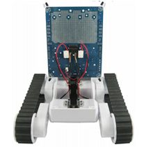
The explorer pcb comes with a built in power supply, and is powered by 6 AA batteries which are housed in the Rover 5 base. The battery pack is connected to the under side of the pcb.
When the batteries have been connected there is a switch on the back of the pcb which can be used to switch the power on and off. The Gadgeteer mainboard can also be powered from this power supply.
I also picked an expansion plate to mount the gadgeteer stuff on
Once i had everything wired up. I created a new visual studio Gadgeteer project. Added the gadgeteer mainboard and extender module to the visual designer and wrote the following code to setup the pwm and digital io pins.
 var leftmotor = extender.SetupPWMOutput(GT.Socket.Pin.Seven);
 var leftMotorDirection = extender.SetupDigitalOutput(GT.Socket.Pin.Five, true);
 var rightmotor = extender .SetupPWMOutput(GT.Socket.Pin.Eight);
 var rightMotorDirection = extender .SetupDigitalOutput(GT.Socket.Pin.Six, true);
I then wrote a simple method to drive the motors by calling the SetPulse method on the pwm pins.
According to the documentation for the motor controller, the high time of the pwm pulse determines the motor power. So 100% high time is 100% power, 50% high time is 50% power and so on.
The period and high time parameters of the SetPulse method have to be provided in nano seconds.
As you can see it's still really simple to drive a motor using a non gadgeteer motor controller.
When i first tested this i wrote a simple program using the Gadgeteer joystick module to drive the motors forwards or backwards depending on which way the joystick was pushed.
Now that i could control the motors, i started working on the object tracking part which i will detail in my next post.
This is my first real project using the awesome .Net gadgeteer platform. My initial aim for this project was to build a Gadgeteer version of the robot shown in this video.
The robot can track objects at short (around 20-30cm) distances and will try to stay a set distance away from the object it is tracking.
For tracking the robot uses an ir compound eye, which is a sensor that gives an analog output depending on the level of reflected infrared light.
This is a video of the working prototype of my gadgeteer powered version. (apologies for the crappy quality, i'll get a better version uploaded soon)
This is the first of a series of posts detailing how i went about building it and the stupid expensive mistakes i made along the way.
Parts and materials
The base of the robot is a Rover 5 chassis, made by Dagu electronics.
I had a couple of different options for the motor controller. GHI electronics make a Gadgeteer motor driver module, which i could have used and would probably have worked perfectly well.
However i chose the
Dagu explorer pcb as it was designed to fit the chassis i was using and has lots of other nice features such as infrared corner tracking and multiple power sources.


.JPG)